OPERATIONS MANUAL
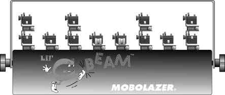
ML8-5R
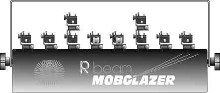
ML8-5G/ML8-20GX
WARNING
READ AND FOLLOW ALL INSTRUCTIONS
CAREFULLY BEFORE OPERATING
THE LASER PROJECTION SYSTEM
![]()
Use of controls or adjustments
or performance of procedures
other than those specified herein
may cause hazardous radiation exposure.
| Introduction |
Congratulations on your purchase of the Mobolazer Laser Projection System. Your new laser is a full-scale laser light projection system harnessed into a compact, air-cooled, low maintenance unit. The Mobolazer Laser Projection System has 8 beam apertures that can be expanded by adding a variety of effect modules. This system uses high quality dichroic optics to minimize light losses. The system is compatible with most DMX-512 controllers that have 8 available channels.
Easy to use, the system sets up in approximately 30 minutes and can be mounted to a standard lighting truss. If desired, it can be synchronized with music. ( Internally in the ML8-5G & ML8-20GX after January 2001. ) Special effects are produced by modular accessories that attach to the apertures located on top of the projection rail. A variety of Mobolazer beam-effect modules can be attached to offer a seemingly endless array of mix-and-match effects.
The system plugs into any standard household outlet with supplied adapter. The CDRH-certified system ( ML8-5R & ML8-5G only ) is compatible with all Mobolazer accessories including the Mobolazer G-Scan graphics system. Mobolazer has manufactured your laser projection system to bring you years of use. Similarly, your owner's guide has been designed with easy-to-follow explanations and directions. Please read all of the instructions regarding your Mobolazer Laser Projection System and retain this manual for future reference.
Thank you for selecting Mobolazer, Inc.
| 1. Safety Considerations |
   |
||||
PLEASE READ ALL INSTRUCTIONS CAREFULLY REGARDING THE SET-UP AND USE OF YOUR MOBOLAZER LASER PROJECTION SYSTEM. FOLLOW ALL WARNINGS AND INSTRUCTIONS. |
||||
| 1. | Follow Instructions | |||
| All set-up and operating instructions should be followed carefully for safe operation of your laser system. | ||||
| 2. | Power Source | |||
| This projection system should be operated only from the type of power source indicated on the power supply of the laser. If you are not sure of the power at your location, consult an electrician or your local power company. | ||||
| 3. | Grounding And Polarization | |||
This system is equipped with a polarized alternating-current line plug. This plug will fit into the power outlet only one way. This is a safety feature. Never bypass any grounding connections on the unit---electric shock may result. |
||||
| 4. | Overloading Circuits | |||
| Do not overload wall outlets and extension cords as this may result in a risk of fire or electrical shock. | ||||
| 5. | Object And Liquid Entry | |||
Never push objects through openings on the projection system as they may touch dangerous voltage points or short-out parts that could result in a fire or electrical shock. Do not spill liquids of any kind on or into the projection system. |
||||
| 6. | Servicing | |||
Do not attempt to service this projection system yourself as opening or removing covers may expose you to dangerous voltage or laser radiation and voids warranty. Refer all servicing to Mobolazer qualified technicians. |
||||
| 7. | Damage Requiring Service | |||
| Unplug the projection system from the outlet and refer servicing to Mobolazer qualified service personnel under the following conditions: | ||||
| * When the power-supply cord or plug is damaged. | ||||
| * If liquid has been spilled or objects have fallen into the projection system. | ||||
| * If the projection system has been exposed to rain or water. | ||||
| * If the projection system does not operate normally by following the operations instructions. Adjust only those controls that are covered in the operating instructions. An improper adjustment of other controls may result in damage and will often require extensive work by a qualified technician to restore the system to its normal operation. | ||||
| * If the projection system has been dropped or the housing has been damaged. | ||||
| *When the projection system exhibits a distinct change in performance - this indicates a need for service. | ||||
| 8. | Power-Cord Protection | |||
| Power-supply cords should be routed so that they are not likely to be walked on or pinched by items placed upon them or against them, paying particular attention to cords at outlets, convenience receptacles, and the point where they exit the projection system. | ||||
| 9. | Beam Modules | |||
| Do not alter the beam effect modules in any way. Do not insert any diffraction unit that is not recommended by Mobolazer into the beam aperture path. | ||||
| 10. | Placement Of The Unit | |||
| Place the unit in an area of the ceiling where the temperature does not exceed 84 degrees F. Temperatures above this have been found to cause the laser's performance to degrade. Install the unit as instructed on a lighting truss capable of handling the additional weight of the projection system, or use the mounting yoke to install the unit on a support beam. Make sure the unit and all accessories are securely fastened so the system does not fall causing injury. | ||||
| 11. | Ventilation | |||
| Slots and openings in the unit housing are provided for ventilation to protect it from overheating and to ensure reliable operation of the projector system. To ensure longevity of the projection system, these openings must not be blocked or covered. | ||||
| 12. | Laser Precautions | |||
| If exposed, the laser's short wavelength poses EXTREME HAZARDS , even at great distances: | ||||
| * Never expose eyes by looking directly into the laser beam. | ||||
| * Never use eyes to align or orient the beam by looking into its source. | ||||
| * Avoid exposure to direct or collateral radiation from the laser. | ||||
| * Make sure that ALL warning labels are in place and easily seen. | ||||
| 13. | Laser Safety | |||
There are several regulations that must be followed when using a laser projection system. Under FDA regulations, any laser system emitting above 1mW must be no closer than 3 meters ( about 10 feet ) above or 2.5 meters ( about 8 feet ) on the sides or below the floor ( such as through a catwalk or grated dance floor ) where an audience would be, and must be under continuous control by a qualified operator. If the system is not under continuous control, double these safety guidelines to comply with FDA standards. Exercise common sense. If you consider the laser beams to be somewhat like a firearm ( the bullet synonymous with the laser beam path ), then it should not be difficult to eliminate the chance of accidental human exposure to laser radiation. Always have an operator present to monitor the safety of the laser projection system. In the unlikely event of a bounce mirror slipping, or a stray beam projecting into an area where human exposure may occur, the operator must immediately shut down the system and correct the problem before continuing with the operation of the laser projection system. Extreme caution must be taken to insure that proper safety procedures are used by the operator during set-up and while the laser projection system is in use. Insure that all beams are terminated in a safe location, and avoid physical contact with the laser beams. |
||||
|
||||
| 2. Unpacking The Laser Projection System |
As you unpack your new laser projection system make sure that all parts are included and are not damaged. ( See packing slip for list of shipped items )*
| A few suggestions: | |
| 1. | Be sure to save the box in which your projection system was shipped. Also save the packing material. In the unlikely event your new projection system must be returned to Mobolazer, it should be transported in it's original box. |
| 2. | Before you hook up the system, please take a few minutes to: |
| * Complete the registration card and send it back to us immediately. | |
| * File your sales receipt in a safe place. | |
| * Write down the serial number and keep it in a safe place for future reference. |
Now that you have unpacked your Mobolazer Laser Projection System and read through the safety information, it's time to become familiar with the system.
Please Note: Mobolazer is not responsible for damage, insufficient parts or failure not reported within 48 hours of receipt.
| 3. Getting To Know The Laser Projection System |
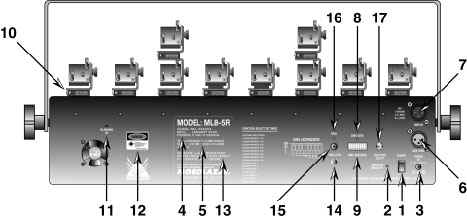
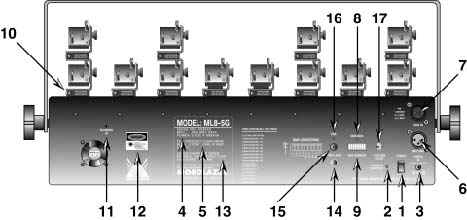
1. |
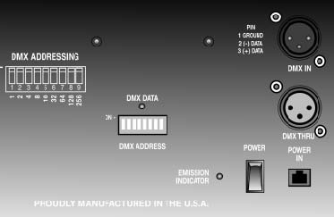
Power Switch - When activated this switch supplies power to the laser system. |
2. |
Emission Indicator LED - Glows red to indicate that the power switch is engaged and the laser is energized. |
3. |
Power In - Mobolazer supplied power pack plugs into this receptacle. Use only the correct power supply to avoid damage to the laser projection system. The correct input voltage is 5vDC, with 1000mA of current. Please make sure the correct adapter configuration is used. |
( Pin = +, Sleeve = - ) |
|
4. |
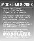
Identification, Serial Number And Manufacture Date Label - Identifies model number, date that the unit was manufactured, as well as it's own unique serial number which is needed for the warranty ( removing this label voids warranty ). See Labeling Requirements for more information. |
5. |
CDRH Conformance Label - Indicates that the Mobolazer Laser Projection System complies with the CDRH ( Center for Device and Radiological Health ) requirements governing laser products manufactured in the United States. See Labeling Requirements for more information. ( Note that the ML8-20GX is not compliant, and is for export use only. ) |
6. |
DMX Thru - Allows another Mobolazer Laser Projection System or other DMX-512 devices to be daisy chained via three pin XLR cables. See Technical Specifications for pin configuration. |
7. |
DMX In - Optically isolated, three-pin DMX input allows for standard DMX-512 data to operate the laser projection system. See Technical Specifications for pin configuration. |
8. |
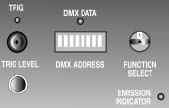
DMX Data LED - A green glow indicates that DMX-512 signal is present. |
9. |
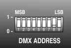
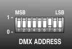
DMX Address Select - Allows user to select DMX-512 address for the Mobolazer Laser Projection System. The address is set in Binary with the right most switch as MSB and the left most switch being the LSB. See DMX-512 Addressing for more information. For systems manufactured before 2001, see Pre-2001 ML8 Series Addendum. |
10. |
Beam Apertures - Laser beams are emitted from these windows, located on the projector rail. |
11. |
Blanking In - Allows the laser to be modulated by an external +5v signal and is primarily intended for the Mobolazer G-Scan Scanning System. |
12. |
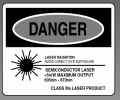
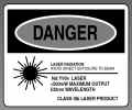
Classification Label - Specifies the type of laser and power. See Labeling Requirements for more information. |
13. |
Non-Interlock Label - CDRH required non-interlock label. Exposure to laser light may occur if panels are removed. See Labeling Requirements for more information. |
14. |
Microphone - Microphone for triggering internal sound activated programs. |
15. |
Trigger Level - Trim pot. for microphone sensitivity and triggering of internal sound active programs. Clock-wise rotation increases sensitivity, counter clock-wise decreases sensitivity. |
16. |
Trigger LED - Red glow indicates a microphone trigger, for internal sound active programs. |
17. |
Function Select - Rotary switch for internal settings. See Function Select Settings. |
| 4. Mounting The Laser Projection System |
To determine the final performance location of your laser projection system, it is necessary to understand the laser and how it functions. Your Mobolazer Laser Projections System incorporates a Class llla, or higher, air-cooled diode, argon or semiconductor laser. Laser light is a narrow and intense beam of light. For a laser beam to be seen, there must be some particles in the air to reflect the light, making the beams visible. ( For example - smoke or haze. ) However, you must be aware that a high volume of particles in the air will scatter the light shaft making it a diffused light source not unlike an incandescent lighting effect. Therefore, if you have smoke effect generators it would be best to wait a few minutes for the smoke to dissipate before you activate the laser light show.
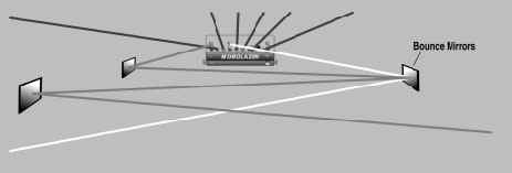
Finding the best placement for the laser projection system and associated mirrors is critical in maximizing the enjoyment of the laser show. To extend the life of the laser unit, the system should be located in an area with at least 12 inches of ventilation space and have adequate air flow. Preferably the system should be located in an area where maximum visibility can be attained. You should be able to see the laser from every corner of your site. The longer the beams can travel, the more the laser is visible to you spectators. The laser should be considered the centerpiece of your lighting effects. To take advantage of this, it would be best to mount the unit in the center of attention, like at the front-center edge of the dance floor, with bounce mirrors high around the corners of the show area.
Once you have decided where the safest ( see Safety Considerations ) and most advantageous location to place the laser projection system, you can then mount the system. This can be done in several ways.
If you have a lighting truss that can support the additional load of the laser projection system, you can mount the system to your truss with standard c-clamps.
The projection system can also be mounted onto non-truss systems through the 1/2" mounting holes on the systems yoke. Secure mounting of the system can also be done easily and inexpensively using components sold in any local hardware store. If you have questions about the safety of the installation, please contact a local contractor or professional for advise or suggestions.
Make sure that the laser projection system is mounted securely and that it will not come loose and thereby cause a safety hazard. Use of safety hardware ( including safety cables ) is strongly recommended. After the system is mounted in its permanent location, install cables for DMX-512 control and power.
| 5. Setting Up The Beam Aperture Modules |
Installation And Removal Of Beam Aperture Modules |
|
1. |
Make sure the laser projection system power switch is turned off |
2. |
Insert the modules as shown in the drawing below. |
3. |
Tighten the aperture block thumb screws on the projector rail until secure. |
4. |
To remove, loosen the thumb screws on the projector rail and pull the modules out. |
Adjustment Of Beam Aperture Modules |
|
After the laser projection system has been mounted, the beam modules need to be aligned. |
|
A standard procedure is as follows: |
|
1. |
Before any beam channels are activated ( via DMX-512 or via Function Select ) loosen the |
Vertical Adjustment Thumb Screws ( 2 ) on the side of each module. |
|
2. |
Adjust all the Dichroic Mirror Mounts ( 3 ) so that the beam will be directed to a safe location. ( Pointing the mounts towards the ceiling is usually the safest direction. ) |
3. |
Turn on the power switch of the laser projection system. |
4. |
Bring up the desired channel, via DMX-512 or Function Select. ( For more information see DMX-512 Addressing or Function Select Settings. ) |
5. |
Lower the Dichroic Mirror Mount ( 3 ) towards it's target. ( With Beam Splitter Modulesstart with the bottom mirror mount, and after all the adjustments have been made, then adjust the top Single Beam Module. ) |
Horizontal Beam Alignment |
|
6. |
Loosen the aperture block thumb screw on the projector rail. |
7. |
Adjust the beam's horizontal direction by turning the module in the aperture block. |
8. |
Tighten aperture block thumb screw. |
Vertical Beam Alignment |
|
9. |
Begin vertical alignment by loosening the Vertical Adjustment Thumb Screw ( 2 ). |
10. |
Move the Dichroic Mirror Mount ( 3 ) vertically until the beam is on target. |
11. |
Tighten the Vertical Adjustment Thumb Screw ( 2 ). |
12. |
To fine tune the alignment, use the Fine Adjustment Thumb Screws ( 1 ) to bring the beam to it's final target. |
| Beam Effect Module | |
| 1. | Fine Adjustment Thumb Screws |
| 2. | Vertical Adjustment Thumb Screw |
| 3. | Dichroic Mirror |
| 4. | Aperture Block ( Beam Splitter Module Only ) |
| 5. | Hub |
| 6. | Diffraction Grating ( Single Beam Diffraction Module Only ) |
| 7. | Horizontal Adjust Thumb Screw |
| 6. DMX-512 Addressing |
The dip-switches located on the back of your laser projection system ( see drawing below ) allow you to set the first DMX-512 channel from which your system will respond to a DMX-512 controller. Please note that your system requires 8 channels of DMX-512. ( See table below. ) Setting the unit to DMX-512 channel 1 means that the system will use DMX-512 channels 1 to 8 for operation. The systems starting channel number is selected by switching ON one or more of the nine dip-switches. Each switch that is turned ON is assigned a binary value. These values are listed on the back of the projector and in the table below. Each switch that is OFF is assigned a value of 0. The DMX-512 starting channel is then determined by adding the values of switches 1 to 9. ( See example below. ) For DMX-512 pin configuration, see Technical Specifications. For ML8-5G and ML8-20GX systems without the Function Select feature, see Pre-2001 ML8 Addendum section.
|
NOTE: ML8-5R -
Multiple apertures can be open at the same time. |
||||||||||||||||||||||||||||||||||||||||||||||||||||||||
DMX-512 Address Examples |
||
DMX-512 Control Address |
System Dip Switches ON |
Binary Values |
7 |
1, 2, 3 |
1 + 2 + 4 = 7 |
50 |
2, 5, 6 |
2 + 16 + 32 = 50 |
198 |
2, 3, 7, 8 |
2 + 4 + 64 + 128 = 198 |
| 7. Function Select Settings |
Using the internal settings, you can operate your laser projector system without the need of an external DMX-512 controller. Use Functions 1 - 8 to safely target your beams or pre-program your scanner. Use Functions 9 - F, only after all safety measures have been followed. See Safety Considerations. If you are using a scanning system, use Functions B, E, and F for best results. Adjust Trigger Level to desired effect by turning clock-wise for increased sensitivity, counterclock-wise for decreased sensitivity.
Select |
Internal Functions |
Description |
0 |
External DMX-512 Control |
See DMX-512 Addressing |
1 |
Aperture 1 On (Furthest Left) |
For Module Focus |
2 |
Aperture 2 On |
For Module Focus |
3 |
Aperture 3 On |
For Module Focus |
4 |
Aperture 4 On |
For Module Focus |
5 |
Aperture 5 On |
For Module Focus |
6 |
Aperture 6 On |
For Module Focus |
7 |
Aperture 7 On |
For Module Focus |
8 |
Aperture 8 On (Furthest Right) |
For Module Focus And Programming Scanner System |
9 |
Sound Active Chase 1 |
Random Laser ON With Trigger ( Laser Stays OFF Until Next Trigger ) |
A |
Sound Active Chase 2 |
Random Laser Chase With Trigger ( Laser Stays ON Until Next Trigger ) |
B |
Sound Active Chase 3 |
Random Laser Chase With Trigger ( Aperture 8 Stays ON With No Trigger ) |
C |
Auto Chase 1 |
Slow Random Chase |
D |
Auto Chase 2 |
Medium Random Chase |
E |
Auto Chase 3 |
Medium Random Chase Alternating With Aperture 8 For Scanner System |
F |
Auto Chase 4 |
Fast Random Chase Alternating With Aperture 8 For Scanner System |
| 8. Service And Maintenance |
It is important to maintain your Mobolazer Laser Projection System in proper operating condition to optomize the life of the laser. It is also important to preform regular checks of the system's cleanliness and ventilation.
Cleaning The Projection System |
|
1. |
Make sure the laser projection system is turned off. |
2. |
Make sure that all ventilation holes and fans are clear of any obstructions such as lint or dirt. |
3. |
Wipe down the system with a damp cloth. If you experience greasy residue or smoke deposits, spray a clean cloth with a solvent such as glass cleaner and wipe down the unit. Be careful not to spill any liquids into the system. |
Cleaning Beam Aperture And Dichroic Mirrors |
|
Now that the projector system has been wiped down, obtain an ample supply of cotton swabs and glass cleaner. These supplies will be necessary for cleaning the small dichroic mirrors on the beam modules and the aperture windows on the projector rail. Here are the steps to clean them: |
|
1. |
Remove all modules. ( See Setting Up The Beam Aperture Modules. ) |
2. |
Saturate a cotton swab with glass cleaner and clean the beam aperture window as illustrated below. A clean aperture window ensures proper passage of the laser beam and full intensity of the system. |
3. |
Apply glass cleaner to the end of a cotton swab, and shake off any excess. NOTE: Be very careful when cleaning the dichroic mirrors as they are very fragile and can break off easily and are not covered by the warranty. With an up and down motion, use one cotton swab for every mirror. Clean the upper mirror first, then the lower mirror. This will ensure that if any dust has settled on the lower mirror, from the cleaning of the upper mirror, it is cleaned off. |
4. |
When cleaning diffraction modules, use distilled water on the inside of the diffraction grating and glass cleaner on the outside of the diffraction grating. Using anything other than distilled water on the inside of the diffraction grating will cause damage to the delicate coating. |
5. |
Reinstall all modules. ( See Setting Up The Beam Aperture Modules. ) |
6. |
Realign all modules. ( See Setting Up The Beam Aperture Modules. ) |
Cleaning Bounce And Diffraction Mirrors
Check the laser projection system frequently. Immediately replace any broken parts, keep all optical components clean, check all cables and strain relief's regularly.
At Mobolazer we take pride in the durability and reliability of our products. A great deal of emphasis has been placed on controlled manufacturing methods and on quality control throughout the manufacturing process. Despite this fact, occasionally projectors break down in operation. We feel that our units have a favorable service record and highly economical prices when compared to other competitors. We hope to demonstrate in the long run, that we always provide the customer with above average service, quality and turn around time. We not only want to ease your economic burden, but also make our facilities available tto get your system operating again in the shortest amount of time possible. If you have any questions please feel free to contact us.
| 9. Technical Specifications |
|
|
||||||||||||||||||||||||||||||||||||||||||||||||||||||||||||||||||||||||||||||||||||||||||||||||||||||||||||||
ML8 - 20GX G-Beam ( For export use only) |
|
8 - Beam apertures with a 20mW green laser |
|
Internal auto chase programs |
|
Internal sound active programs |
|
Internal beam selection |
|
G-Scan compatible |
|
DMX-512 Controllable |
|
-8 - Channels DMX-512 |
|
-Optically isolated DMX-512 interface |
|
ML8 Series modules included |
|
-6 - Single beam |
|
-4 - Beam splitters |
|
-2 - Diffraction beam |
|
CE Certified |
|
Patent pending |
|
Power supply |
|
Input - Determined on individual export power specifications. |
|
Output to system - 5vDC/1000mA |
|
Pin = +, Sleeve = - |
|
Dimensions - 24.5" w x 1.75" d x 10" h |
|
Weight - 7 Lbs. |
|
| DMX-512 Pin Configuration | |||||||||||||||||
 |
|
||||||||||||||||
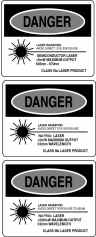
| 10. Labeling Requirements |
| ML8-5R R-Beam | ML8-5G G-Beam | |
| Located On Rear Of
Projector Laser System
Identification |
 |
 |
| Located On Rear Of
Projector Laser
Classification Warning |
 |
 |
| Located On Top Of
Projector Rail & On Top Of Beam Splitter Module Aperture Warning Label |
 |
|
| ML8-20GX G-Beam ( For Export Use Only ) | ||
| Located On Rear Of
Projector Laser System
Identification |
 |
|
| Located On Rear Of
Projector Laser
Classification Warning |
 |
|
| Located On Top Of
Projector Rail & On Top Of Beam Splitter Module Aperture Warning Label |
|
|
| 11. Pre-2001 ML8 Series Addendum |
NOTE: This section is only intended for ML8-5G and ML8-20GX units that DO NOT have the Function Select feature. ( Manufactured before January 2001. ) If your laser projection system has been manufactured with the Function Select feature, please see the DMX-512 Addressing and the Function Select Settings sections of this manual.
DMX-512 Addressing
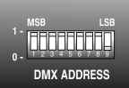
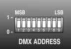
The dip-switches located on the back of your laser projection system ( see drawing below ) allow you to set the first DMX-512 channel from which your system will respond to a DMX-512 controller. Please note that your system requires 8 channels of DMX-512. ( See table below. ) Setting the unit to DMX-512 channel 1 means that the system will use DMX-512 channels 1 to 8 for operation. The systems starting channel number is selected by switching ON one or more of the nine dip-switches. Each switch that is turned ON is assigned a binary value. These values are listed on the back of the projector and in the table below. Each switch that is OFF is assigned a value of 0. The DMX-512 starting channel is then determined by adding the values of switches 1 to 9. ( See example below. ) For DMX-512 pin configuration, see Technical Specifications.
|
|
|||||||||||||||||||||||||||||||||||||||||||||||
| *NOTE ML8-5G -
Only one aperture can be open any time ML8-20GX - Multiple apertures can be open at the same time |
DMX-512 Address Examples |
||
DMX-512 Control Address |
System Dip Switches ON |
Binary Values |
7 |
9, 8, 7 |
1 + 2 + 4 = 7 |
50 |
8, 5, 4 |
2 + 16 + 32 = 50 |
198 |
8, 7, 3, 2 |
2 + 4 + 64 + 128 = 198 |
Stand Alone Dip Switch Configurations
With just a few simple dip-switch setting changes you can operate the ML8 series laser projectors without the use of a DMX-512 controller.
Below are lists of dip-switch settings that adjust the internal chase speed of your laser projection system. You will notice that there are two different sets of three settings. The first set of three operates your projector without a scanning system.
If you are operating a scanning system such as a Mobolazer SC-100 or G-Scan System, you will want to use the second set of dip-switch settings. These pre-programmed chase patterns will activate aperture 8 every other step to simulate the scanner system being on constant, and while chasing other apertures. ( Aperture 8 is furthest right when facing the front of the unit. )
| Without Scanning
System ( Standard Module On Aperture 8 ) |
With Scanning System ( Scanner On Aperture 8 ) |
|
Slow Chase |
 |
 |
Medium Chase |
 |
 |
Fast Chase |
 |
 |
The ML8 series laser projector is very impressive with the "stand-alone" modes of operation. However, for ease of bounce mirror targeting and for scan only operation, you should invest in a simple DMX-512 controller. Please contact an authorized Mobolazer dealer for more control options and information.
| 12. Warranty |
MOBOLAZER ML8 Limited Warranty
Mobolazer, Inc. warrants that the ML8 Series Laser Projectors are shipped from the factory free from defective materials and workmanship with a limited warranty under normal use and service of three (3) years from the date of purchase. Lasers, modules, and accessories are warranted for one (1) year from the date of purchase to the original end user when purchased from an authorized Mobolazer, Inc. dealer and is not transferable. This express warranty is provided by Mobolazer Inc. 790 Hampshire Road, Unit D, Thousand Oaks, California 91361.
THIS WARRANTY IS GIVEN IN LIEU OF ALL OTHER WARRANTIES, EXPRESSED OR IMPLIED. INCLUDING, WITHOUT LIMITATION, IMPLIED WARRANTIES OF MERCHANTABILITY AND FITNESS FOR PARTICULAR PURPOSE. IN NO EVENT SHALL MOBOLAZER BE LIABLE FOR ANY LOSS OF USE, LOSS OF TIME, COMMERCIAL LOSS, LOST PROFITS OR SAVINGS OR OTHER INCIDENTAL, SPECIAL OR CONSEQUENTIAL DAMAGES ARISING OUT OF THE USE OR INABILITY TO USE SUCH PRODUCT, TO THE FULL EXTENT SUCH MAY BE DISCLAIMED BY LAW
This warranty sets forth the full extent of Mobolazer, Inc. responsibilities regarding product repair or replacement as the exclusive remedy.
In the event of a defect, malfunction, or failure to conform to specifications during the warranty period, Mobolazer, Inc., at its option, will either repair, or replace parts or boards with functionally equivalent new or reconditioned parts or boards. Replaced parts and boards are warranted for the balance of the original warranty period. All parts and boards removed in the replacement process shall become the property of Mobolazer, Inc. Transportation charges to and from an authorized dealer or the Mobolazer factory for repair shall be the responsibility of the owner. All products returned to Mobolazer, Inc. must have a factory return authorization number (RA) for return prior to shipping. For further information and special shipping instructions, please call (888) 555-5555.
This warranty does not cover defects, malfunctions, performance failures or damage to the unit resulting from use in other than normal and customary manner, misuse, accident or neglect, the use of non-conforming parts, or improper alterations or repairs. This warranty does not cover wear and tear on covers, housings, items such as knobs, jacks and switches, and optical components including mirrors, diffraction gratings, and windows.
WARRANTY WILL BE VOID IF ANY OF THE FOLLOWING CONDITIONS OCCUR:
The purchaser is responsible for completing and mailing to Mobolazer, Inc. within fifteen (15) days of purchase the warranty registration card enclosed with each product.
SOME STATES DO NOT ALLOW THE EXCLUSION OR LIMITATION OF INCIDENTAL OR CONSEQUENTIAL DAMAGES, OR LIMITATION ON HOW LONG AN IMPLIED WARRANTY LASTS, THEREFORE THE ABOVE LIMITATIONS OR EXCLUSIONS MAY NOT APPLY. This warranty gives you specific legal rights and you may have other rights, which vary, from state to state.
